Results of 6.64 mile 5.885GHz signal test

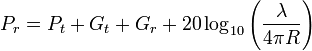
We managed to get actual line-of-sight conditions this time, so these results are valid. Big thanks to Cory (NQ1E) and David (KB7ILD) for helping to do the experiments. *Calibrated Measurements* Distance = 6.64mi (10,686m) Ant 1 gain = 32dBi Ant 2 gain = 30dBi TX power: +10dBm RX power: -80.5dBm Cable losses: 5dB ? Link Loss = 90.5dB ? Link Loss without cables = 85.5dB This represents an error of about 14dB from the predictions made using the Friis transmission equation <http://en.wikipedia.org/wiki/Friis_transmission_equation>: P_r = P_t + G_t + G_r + 20\log_{10}\left( \frac{\lambda}{4 \pi R} \right) ? 5+32+30+20*log(0.050977/(4*Pi*10686))/log(10) %30 = -61.413015204884308993536006145086600724 In the above calculation, the cable losses have been subtracted from the transmit power, leaving just +5dBm. The result is that -61dBm is predicted to be seen as the received power. In reality, the cable-loss-adjusted receive power was -75.5dBm, a difference of about 14dB. I'm not sure where this error is coming from. The formula's dependence on wavelength is weird. The physical explanation <http://en.wikipedia.org/wiki/Free-space_path_loss#Physical_explanation> here is confusing. Is there some implied expression here for aperture size? I've always regarded isotropic antennas as point source concepts with no aperture size at all, and yet the frequency dependence of this formula seems to be explained by aperture size of isotropic antennas. WTF. If anyone has any better propagation models, or an explanation of what's going on here, please do share! In the meantime, we need to figure out what's going on with this 14dB error. Is it a constant error (good), or is it a factor of distance (bad)? To answer this we must do another test at a different (preferably longer) distance between the TX and RX sites, under line-of-sight conditions. In essence we're experimentally deriving the propagation model through our measurements here, since the textbook model does not seem to fit real world results. Go science! *Modem Measurements* After we got the calibrated measurements out of the way, we then disconnected the RF cables and attached two Metal 5SHPn modems (set for +31dBm TX) directly to the antennas. The power level was therefore increased by 21dB due to raw power increase and an additional 5dB due to elimination of lossy feedlines. This means 26dB more power. This means that the previous RX power of -80.5dBm should increase by 26dB to give -54.5dBm readings. And guess what showed up in the Metal 5SHPn RSSI readings? -55dBm! BANG ON ACCURATE. Once again, go science! :) At this power level, the link quality was 100% and we were able to move data at full speeds (about 57Mbit) in both directions. *Sector Prediction* Keep in mind all this was done with high gain PtP antennas over a mere 6.64 mile span. Full speed is expected. The performance of the system in PtMP mode will be much lower. The sector antenna gain is 16dB lower than the high gain TX antenna we were using. That nice -55dBm would become -71dBm. The modems are specified to hold full speed down to -77dBm, so we've got 6dB of link budget left before things start slowing down. This corresponds to (hopefully) a doubling of the 6.64 mile distance to ~13mi for full-speed PtMP coverage radius. The previous statement assumes that the 14dB model error is a constant error and not distance-related. Cross your fingers! The minimum operating level of the modems is -93dBm, which is 16dB below the signal limit of the full-speed level. Luckily this represents at least two 6dB distance-doublings, so as long as the 14dB error is not distance-related and the theoretical formulas hold, we could see slow-speed (6Mbit) PtMP links as far as 52 miles away from a sector antenna. *Transmit Power Levels* All the previous Sector Prediction depends on a transmit power of +31dBm. Due to the nature of OFDM and the quality of amplifier found in the Metal 5SHPn modem, this power level does have significant out of band emissions as measured here: https://www.hamwan.org/t/tiki-index.php?page=RouterBoard+Metal+5SHPn&structu... These emissions cause problems with adjacent sectors that are mounted a few feet away and trying to listen for -93dBm signals from clients! Work is underway to improve isolation between antennas (shields, spacing) but TX power may have to be reduced to lower this self-interference and therefore raise the RX sensitivity of the sectors. Any reduction in TX power levels will have a direct impact on range and speed of the system. Another method of combating this splatter is to run the modems at a low enough level that keeps their internal amplifiers from clipping, and then augment the lost power with an external amplifier. This is a cost-prohibitive option though. --Bart
participants (1)
-
 Bart Kus